![]()
![]()

Safari Turbocharger System STHZJ70N
| Parts List | ||||||||||||||||||||||||||||||||||||||||||||||||||||||||||||||||||||||||||||||||||||||||||||||||||||||||||||||||||||||||||||||||||||||||||||||||||||||||||||||||||||||||||||||||||||||||||||||||||||||||||||||||||||||||||||||||||||||||||||||||||||||||||||||||||||||||||||||||||||||||||||||||||||||||||||||||||||||||||||||||||||||||||||||
|
||||||||||||||||||||||||||||||||||||||||||||||||||||||||||||||||||||||||||||||||||||||||||||||||||||||||||||||||||||||||||||||||||||||||||||||||||||||||||||||||||||||||||||||||||||||||||||||||||||||||||||||||||||||||||||||||||||||||||||||||||||||||||||||||||||||||||||||||||||||||||||||||||||||||||||||||||||||||||||||||||||||||||||||
| Installation Guide | ||||||||||||||||||||||||||||||||||||||||||||||||||||||||||||||||||||||||||||||||||||||||||||||||||||||||||||||||||||||||||||||||||||||||||||||||||||||||||||||||||||||||||||||||||||||||||||||||||||||||||||||||||||||||||||||||||||||||||||||||||||||||||||||||||||||||||||||||||||||||||||||||||||||||||||||||||||||||||||||||||||||||||||||
| 1 | Special Tools
|
|||||||||||||||||||||||||||||||||||||||||||||||||||||||||||||||||||||||||||||||||||||||||||||||||||||||||||||||||||||||||||||||||||||||||||||||||||||||||||||||||||||||||||||||||||||||||||||||||||||||||||||||||||||||||||||||||||||||||||||||||||||||||||||||||||||||||||||||||||||||||||||||||||||||||||||||||||||||||||||||||||||||||||||
| 2 | Disconnect the negative (-ve) battery terminal.
Remove the following in accordance with the factory service manual:
|
|||||||||||||||||||||||||||||||||||||||||||||||||||||||||||||||||||||||||||||||||||||||||||||||||||||||||||||||||||||||||||||||||||||||||||||||||||||||||||||||||||||||||||||||||||||||||||||||||||||||||||||||||||||||||||||||||||||||||||||||||||||||||||||||||||||||||||||||||||||||||||||||||||||||||||||||||||||||||||||||||||||||||||||
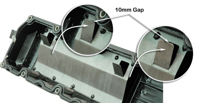
| 3 | Remove the rocker cover.
Push on the PCV baffle tabs to close the gap to 10mm as shown. Reinstall the rocker cover. |
 |
||||||||||||||||||||||||||||||||||||||||||||||||||||||||||||||||||||||||||||||||||||||||||||||||||||||||||||||||||||||||||||||||||||||||||||||||||||||||||||||||||||||||||||||||||||||||||||||||||||||||||||||||||||||||||||||||||||||||||||||||||||||||||||||||||||||||||||||||||||||||||||||||||||||||||||||||||||||||||||||||||||||||||||
| 4 | Remove the exhaust engine pipe.
Remove and discard the engine pipe support bracket. NOTE: The nuts retaining the engine pipe to the exhaust manifold may be seized and require attention (penetrating lubricant or heat) to avoid breaking the exhaust manifold outlet flange studs. |
 |
||||||||||||||||||||||||||||||||||||||||||||||||||||||||||||||||||||||||||||||||||||||||||||||||||||||||||||||||||||||||||||||||||||||||||||||||||||||||||||||||||||||||||||||||||||||||||||||||||||||||||||||||||||||||||||||||||||||||||||||||||||||||||||||||||||||||||||||||||||||||||||||||||||||||||||||||||||||||||||||||||||||||||||
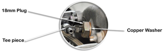
| 5 | Remove the PCV tube from the intake duct
Tap the hole square to the boss in the duct with a M18x1.5 thread tap. Non EGR: Install the 18mm plug (Item 34), copper washer (Item 35). Apply hydraulic thread sealer to the 90 deg adaptor (Item 37) and install into the plug (Item 34). Note orientation. With EGR: Install the 18mm plug (Item 34), copper washer (Item 35). Apply hydraulic thread sealer to the Tee piece (Item 36) and install into the plug (Item 34). Note orientation. |

|
||||||||||||||||||||||||||||||||||||||||||||||||||||||||||||||||||||||||||||||||||||||||||||||||||||||||||||||||||||||||||||||||||||||||||||||||||||||||||||||||||||||||||||||||||||||||||||||||||||||||||||||||||||||||||||||||||||||||||||||||||||||||||||||||||||||||||||||||||||||||||||||||||||||||||||||||||||||||||||||||||||||||||||
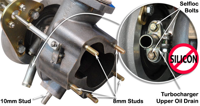
| 6 | Remove the three studs shown from the exhaust manifold
Install three new M10x1.25x23.5mm stainless steel studs (Item 1). |
 |
||||||||||||||||||||||||||||||||||||||||||||||||||||||||||||||||||||||||||||||||||||||||||||||||||||||||||||||||||||||||||||||||||||||||||||||||||||||||||||||||||||||||||||||||||||||||||||||||||||||||||||||||||||||||||||||||||||||||||||||||||||||||||||||||||||||||||||||||||||||||||||||||||||||||||||||||||||||||||||||||||||||||||||
| 7 | Install the actuator mounting spacers (Item 52) to the wastegate actuator/rod assembly (Item 55) and then install the wastegate actuator assembly to the actuator mounting bracket (Item 48) with the actuator vent hole orientated as shown.
Retain with 6mm washers (Item 53) and 6mm Nyloc nuts (Item 54). Install the wastegate assembly to the turbocharger compressor housing. Retain with 8mm bolts (Item 49), apply hydraulic sealant to bolt threads, 8mm star washer (Item 50) and 8mm flat washer (Item 51). Ensure that the wastegate actuator rod is in the centre of the actuator mounting bracket hole when the end of the rod is positioned upon the wastegate swing valve crank arm. |
 |
||||||||||||||||||||||||||||||||||||||||||||||||||||||||||||||||||||||||||||||||||||||||||||||||||||||||||||||||||||||||||||||||||||||||||||||||||||||||||||||||||||||||||||||||||||||||||||||||||||||||||||||||||||||||||||||||||||||||||||||||||||||||||||||||||||||||||||||||||||||||||||||||||||||||||||||||||||||||||||||||||||||||||||
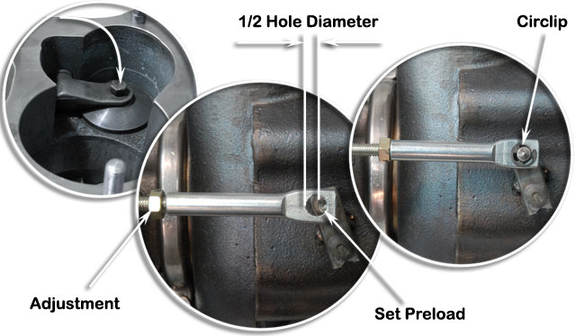
| 8 | Close the wastegate swing valve and adjust the wastegate actuator rod length to achieve a 1/2 hole diameter preload as shown.
Install the circlip (Item 56) to the wastegate swing valve crank arm.
|
 |
||||||||||||||||||||||||||||||||||||||||||||||||||||||||||||||||||||||||||||||||||||||||||||||||||||||||||||||||||||||||||||||||||||||||||||||||||||||||||||||||||||||||||||||||||||||||||||||||||||||||||||||||||||||||||||||||||||||||||||||||||||||||||||||||||||||||||||||||||||||||||||||||||||||||||||||||||||||||||||||||||||||||||||
| 9 | Install the five 8mm studs (Item 8) to the turbine outlet flange.
Install the 10mm stainless steel stud (Item 63) to the turbine housing. Install the turbocharger upper oil drain (Item 80) and gasket (Item 81). Retain with two 6mm selfloc bolts (Item 82). NOTE: DO NOT use any silicon sealing compound on the oil drain gasket surfaces. |
 |
||||||||||||||||||||||||||||||||||||||||||||||||||||||||||||||||||||||||||||||||||||||||||||||||||||||||||||||||||||||||||||||||||||||||||||||||||||||||||||||||||||||||||||||||||||||||||||||||||||||||||||||||||||||||||||||||||||||||||||||||||||||||||||||||||||||||||||||||||||||||||||||||||||||||||||||||||||||||||||||||||||||||||||
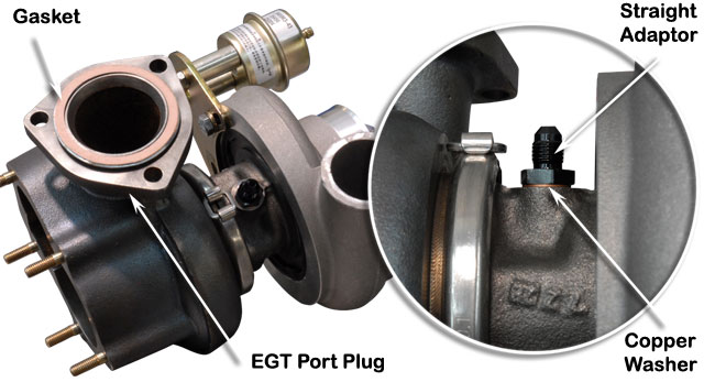
| 10 | Install the 7/16" straight adaptor (Item 78) and 10mm copper washer (Item 79).
Install the EGT port plug (Item 43) (If not already factory fitted). Apply a small amount of high temperature sealant to both faces of the exhaust gasket (Item 42). Install the exhaust gasket (42) to the turbine housing inlet flange. |
 |
||||||||||||||||||||||||||||||||||||||||||||||||||||||||||||||||||||||||||||||||||||||||||||||||||||||||||||||||||||||||||||||||||||||||||||||||||||||||||||||||||||||||||||||||||||||||||||||||||||||||||||||||||||||||||||||||||||||||||||||||||||||||||||||||||||||||||||||||||||||||||||||||||||||||||||||||||||||||||||||||||||||||||||
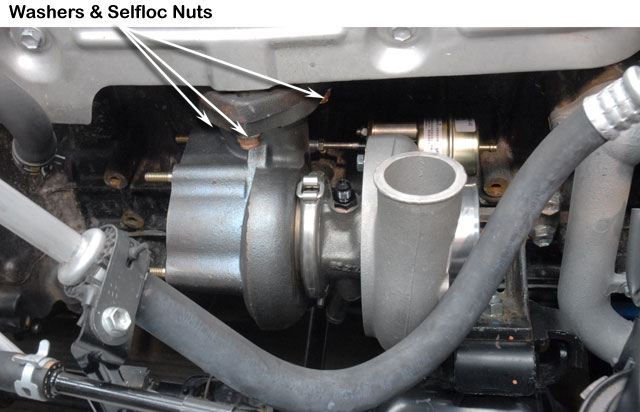
| 11 | Install the turbocharger assembly to the studs (Item 1) on the exhaust manifold.
Retain with washers (Item 3) and 10mm selfloc nuts (Item 2). |
 |
||||||||||||||||||||||||||||||||||||||||||||||||||||||||||||||||||||||||||||||||||||||||||||||||||||||||||||||||||||||||||||||||||||||||||||||||||||||||||||||||||||||||||||||||||||||||||||||||||||||||||||||||||||||||||||||||||||||||||||||||||||||||||||||||||||||||||||||||||||||||||||||||||||||||||||||||||||||||||||||||||||||||||||
| 12 | Install the 18mm copper washer (Item 12) and 18mm hex plug (Item 11) to the turbine outlet pipe (Item 4). | 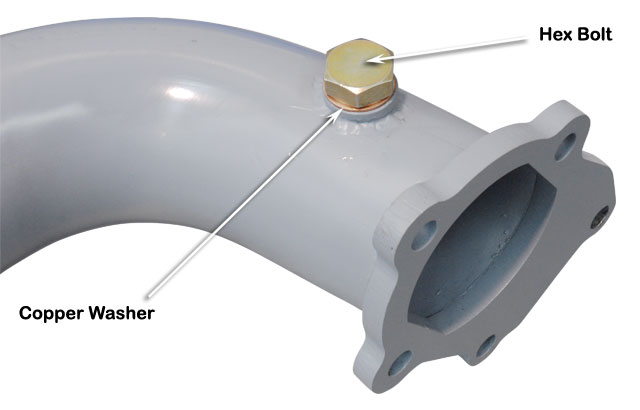 |
||||||||||||||||||||||||||||||||||||||||||||||||||||||||||||||||||||||||||||||||||||||||||||||||||||||||||||||||||||||||||||||||||||||||||||||||||||||||||||||||||||||||||||||||||||||||||||||||||||||||||||||||||||||||||||||||||||||||||||||||||||||||||||||||||||||||||||||||||||||||||||||||||||||||||||||||||||||||||||||||||||||||||||
| 13 | Apply a bead of High Temperature RTV Silicon Sealant to the turbo outlet flange as shown. | 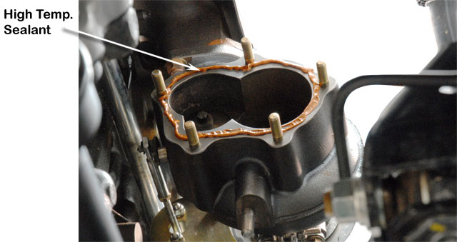 |
||||||||||||||||||||||||||||||||||||||||||||||||||||||||||||||||||||||||||||||||||||||||||||||||||||||||||||||||||||||||||||||||||||||||||||||||||||||||||||||||||||||||||||||||||||||||||||||||||||||||||||||||||||||||||||||||||||||||||||||||||||||||||||||||||||||||||||||||||||||||||||||||||||||||||||||||||||||||||||||||||||||||||||
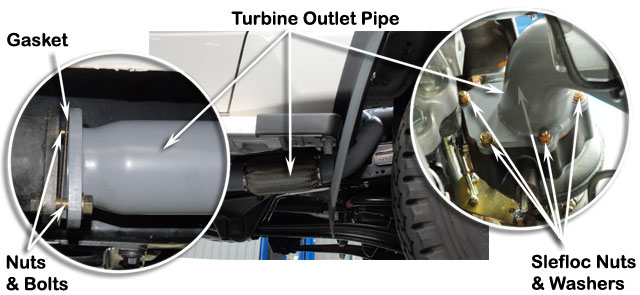
| 14 |
Install the turbine outlet pipe to the turbocharger outlet and retain with 8mm flat washers (Item 10) and 8mm Selfloc nuts (Item 9). Install the 2-bolt flange gasket (Item 5) between the exhaust pipe and the turbine outlet pipe (Item 4) and retain with 10mm x 35mm bolts (Item 6), 10mm flat washers (Item 3) and 10mm flanged nuts (Item 7). |
 |
||||||||||||||||||||||||||||||||||||||||||||||||||||||||||||||||||||||||||||||||||||||||||||||||||||||||||||||||||||||||||||||||||||||||||||||||||||||||||||||||||||||||||||||||||||||||||||||||||||||||||||||||||||||||||||||||||||||||||||||||||||||||||||||||||||||||||||||||||||||||||||||||||||||||||||||||||||||||||||||||||||||||||||
| Turbocharger Oil Drain - Option A - Drain into Engine Oil Pan | ||||||||||||||||||||||||||||||||||||||||||||||||||||||||||||||||||||||||||||||||||||||||||||||||||||||||||||||||||||||||||||||||||||||||||||||||||||||||||||||||||||||||||||||||||||||||||||||||||||||||||||||||||||||||||||||||||||||||||||||||||||||||||||||||||||||||||||||||||||||||||||||||||||||||||||||||||||||||||||||||||||||||||||||
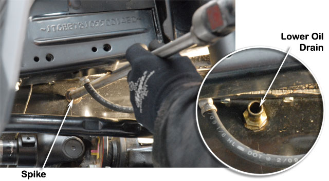
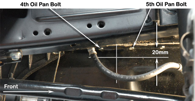
| 15a | Mark the position of the lower oil drain hole which is:
From the rear, between the 4th and 5th oil pan retaining bolts and 20mm down from the oil pan mounting flange as shown. |
 |
||||||||||||||||||||||||||||||||||||||||||||||||||||||||||||||||||||||||||||||||||||||||||||||||||||||||||||||||||||||||||||||||||||||||||||||||||||||||||||||||||||||||||||||||||||||||||||||||||||||||||||||||||||||||||||||||||||||||||||||||||||||||||||||||||||||||||||||||||||||||||||||||||||||||||||||||||||||||||||||||||||||||||||
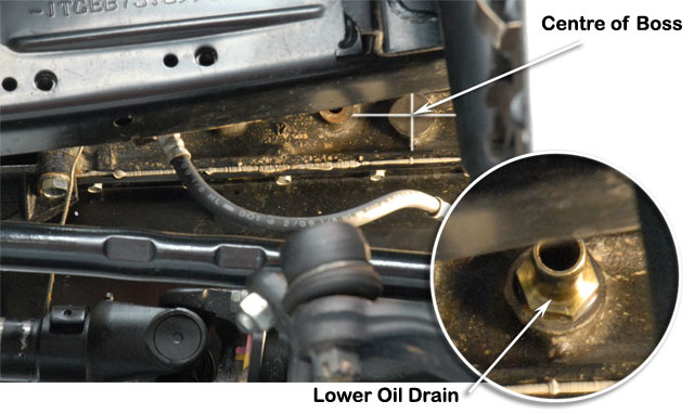
| 16a |
Use a sump spike to punch a hole into the oil pan. Apply grease to the 3/8" BSPF tap and tap hole. Note that the grease is used to prevent swarf from entering the engine oil pan. Clean the tapped area of the oil pan and apply 5 minute Araldite or similar fast setting adhesive to the threads of the lower oil drain (Item 86) and install into the engine oil pan. |
|
||||||||||||||||||||||||||||||||||||||||||||||||||||||||||||||||||||||||||||||||||||||||||||||||||||||||||||||||||||||||||||||||||||||||||||||||||||||||||||||||||||||||||||||||||||||||||||||||||||||||||||||||||||||||||||||||||||||||||||||||||||||||||||||||||||||||||||||||||||||||||||||||||||||||||||||||||||||||||||||||||||||||||||
| Turbocharger Oil Drain - Option B - Drain into Engine Block | ||||||||||||||||||||||||||||||||||||||||||||||||||||||||||||||||||||||||||||||||||||||||||||||||||||||||||||||||||||||||||||||||||||||||||||||||||||||||||||||||||||||||||||||||||||||||||||||||||||||||||||||||||||||||||||||||||||||||||||||||||||||||||||||||||||||||||||||||||||||||||||||||||||||||||||||||||||||||||||||||||||||||||||||
| 15b | NOTE: Apply a generous amount of grease to each drill bit to prevent swarf from entering the engine.
Drill a pilot hole squarely into the engine block assembly in the position shown. Use progressively larger diameter drills to drill to 15mm. Thread the hole with a 3/8" BSPF thread tap. Apply hydraulic sealant to the threads on the lower oil drain (Item 86) and install the lower oil drain (Item 86) into the engine block. |
 |
||||||||||||||||||||||||||||||||||||||||||||||||||||||||||||||||||||||||||||||||||||||||||||||||||||||||||||||||||||||||||||||||||||||||||||||||||||||||||||||||||||||||||||||||||||||||||||||||||||||||||||||||||||||||||||||||||||||||||||||||||||||||||||||||||||||||||||||||||||||||||||||||||||||||||||||||||||||||||||||||||||||||||||
| 17 | Install No.23 spring hose clamps (Item 85) to each end of the oil drain hose and install the oil drain hose
Option A - Item 84 (shown) Option B - Item 83 (not shown) between the turbocharger upper drain (Item 80) and the lower drain (Item 86). Move the spring hose clamps (Item 85) to secure the oil drain hose. |
 |
||||||||||||||||||||||||||||||||||||||||||||||||||||||||||||||||||||||||||||||||||||||||||||||||||||||||||||||||||||||||||||||||||||||||||||||||||||||||||||||||||||||||||||||||||||||||||||||||||||||||||||||||||||||||||||||||||||||||||||||||||||||||||||||||||||||||||||||||||||||||||||||||||||||||||||||||||||||||||||||||||||||||||||
| 18 | Install the turbocharger support bracket (Item 59) to the engine block and retain loosely with 12mm x 25mm bolts (Item 60), 12mm spring washer (Item 61) and 12mm flat washer (Item 62). NOTE Do not tighten bolts yet.
Retain the turbocharger support bracket to the turbocharger with a 10mm flat washer (Item 64) and 10mm selfloc nut (Item 65) to the 10mm stud (Item 63) previously installed on the turbocharger. Align the turbocharger support bracket (Item 59) and tighten all mounting hardware evenly. NOTE: Some engine blocks do not have tapped holes in place. If so, hold the turbocharger support bracket in place and mark the position of each hole on the bosses cast into the block. Drill and tap to M12x1.25 at a depth of 20mm maximum. |
 |
||||||||||||||||||||||||||||||||||||||||||||||||||||||||||||||||||||||||||||||||||||||||||||||||||||||||||||||||||||||||||||||||||||||||||||||||||||||||||||||||||||||||||||||||||||||||||||||||||||||||||||||||||||||||||||||||||||||||||||||||||||||||||||||||||||||||||||||||||||||||||||||||||||||||||||||||||||||||||||||||||||||||||||
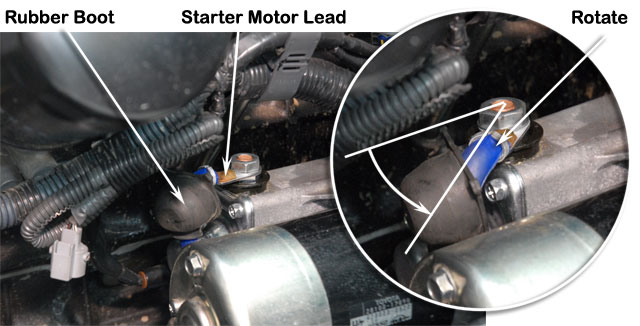
| 19 | WARNING: Ensure that the battery is disconnected.
Pull the rubber boot back from starter motor lead shown and loosen the terminal nut. Rotate the lead 45 deg away from the engine block and re-tighten the terminal nut. Refit the rubber boot. |
 |
||||||||||||||||||||||||||||||||||||||||||||||||||||||||||||||||||||||||||||||||||||||||||||||||||||||||||||||||||||||||||||||||||||||||||||||||||||||||||||||||||||||||||||||||||||||||||||||||||||||||||||||||||||||||||||||||||||||||||||||||||||||||||||||||||||||||||||||||||||||||||||||||||||||||||||||||||||||||||||||||||||||||||||
| 20 | Unplug the oil pressure sender wire from the oil pressure sender unit and remove the oil pressure sender unit from the engine block.
Apply hydraulic sealant to the threads of the oil supply adaptor (Item 71) and install the adaptor into the engine block. Note orientation of hole shown. Apply hydraulic sealant to the threads of the oil pressure sender unit and install the oil pressure sender unit to the adaptor (Item 71). Reconnect the oil pressure sender wire to the oil pressure sender unit. |
 |
||||||||||||||||||||||||||||||||||||||||||||||||||||||||||||||||||||||||||||||||||||||||||||||||||||||||||||||||||||||||||||||||||||||||||||||||||||||||||||||||||||||||||||||||||||||||||||||||||||||||||||||||||||||||||||||||||||||||||||||||||||||||||||||||||||||||||||||||||||||||||||||||||||||||||||||||||||||||||||||||||||||||||||
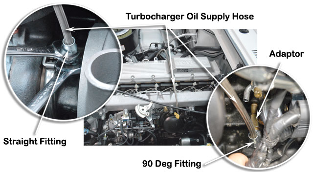
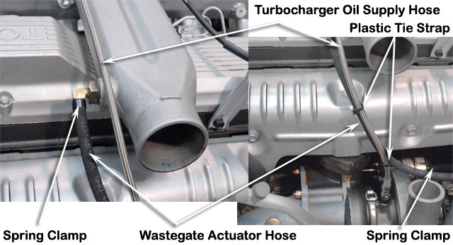
| 21 | Install the 90 deg fitting end of turbocharger oil supply hose (Item 72) to the oil sender unit adaptor (Item 71).
Install the straight fitting end of the turbocharger oil supply hose (Item 72) to the turbocharger oil supply adaptor (Item 78) installed previously. Note: Use two wrenches - one wrench to stop the hose from turning whilst tightening the straight fitting with the other wrench. |
 |
||||||||||||||||||||||||||||||||||||||||||||||||||||||||||||||||||||||||||||||||||||||||||||||||||||||||||||||||||||||||||||||||||||||||||||||||||||||||||||||||||||||||||||||||||||||||||||||||||||||||||||||||||||||||||||||||||||||||||||||||||||||||||||||||||||||||||||||||||||||||||||||||||||||||||||||||||||||||||||||||||||||||||||
| 22 | Install the intake duct back onto the engine. |  |
||||||||||||||||||||||||||||||||||||||||||||||||||||||||||||||||||||||||||||||||||||||||||||||||||||||||||||||||||||||||||||||||||||||||||||||||||||||||||||||||||||||||||||||||||||||||||||||||||||||||||||||||||||||||||||||||||||||||||||||||||||||||||||||||||||||||||||||||||||||||||||||||||||||||||||||||||||||||||||||||||||||||||||
| 23 | Install a spring hose clamp (Item 58) to each end of the 1/4" wastegate actuator hose (Item 57) and install the hose to the wastegate actuator port (Item 55).
Install the other end of the 1/4" wastegate actuator hose (Item 57) to the Non EGR: 90 deg adaptor (Item 37) installed previously. With EGR: Tee piece (Item 36) installed previously. Support the 1/4" wastegate actuator hose along the turbocharger oil supply hose (Item 72) with the three cable ties (Item 77). |
 |
||||||||||||||||||||||||||||||||||||||||||||||||||||||||||||||||||||||||||||||||||||||||||||||||||||||||||||||||||||||||||||||||||||||||||||||||||||||||||||||||||||||||||||||||||||||||||||||||||||||||||||||||||||||||||||||||||||||||||||||||||||||||||||||||||||||||||||||||||||||||||||||||||||||||||||||||||||||||||||||||||||||||||||
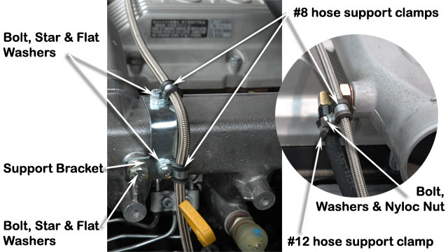
| 24 | Non EGR: Install the oil supply hose support bracket (Item 87) to the intake manifold with a 8x16mm bolt (Item 73), 8mm star washer (Item 75) and 8mm flat washer (Item 74).
Install the two 8/12mm hose support clamps (Item 88) to the oil supply hose (Item 72) and fasten to the oil supply hose support bracket (Item 87) with two 5x12mm hex bolts (Item 89) and 5mm washers (Item 90). Install one 12/15mm hose support clamp (Item 91) to the 1/4" wastegate actuator hose (Item 57) next to the 90 deg adaptor (Item 37) installed previously Install a 8/12mm hose support clamp (Item 88) to the oil supply hose (Item 72) and fasten the two clamps together with a 5x20mm bolt (Item 92), two 5mm flat washers (Item 90) and a 5mm nyloc nut (Item 93). |
 |
||||||||||||||||||||||||||||||||||||||||||||||||||||||||||||||||||||||||||||||||||||||||||||||||||||||||||||||||||||||||||||||||||||||||||||||||||||||||||||||||||||||||||||||||||||||||||||||||||||||||||||||||||||||||||||||||||||||||||||||||||||||||||||||||||||||||||||||||||||||||||||||||||||||||||||||||||||||||||||||||||||||||||||
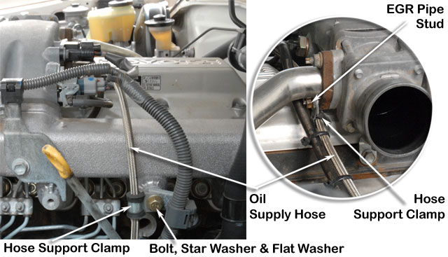
| 24-EGR | With EGR: Install a 8/20mm hose support clamp (Item 76) to the oil supply hose (Item 72) and fasten to the intake manifold with a 8x16mm bolt (Item 73), 8mm star washer (Item 75) and 8mm flat washer (Item 74).
Install a 8/20mm hose support clamp (Item 76) to the oil supply hose (Item 72) and fasten to the EGR pipe stud shown and retain with the standard fastener. |
 |
||||||||||||||||||||||||||||||||||||||||||||||||||||||||||||||||||||||||||||||||||||||||||||||||||||||||||||||||||||||||||||||||||||||||||||||||||||||||||||||||||||||||||||||||||||||||||||||||||||||||||||||||||||||||||||||||||||||||||||||||||||||||||||||||||||||||||||||||||||||||||||||||||||||||||||||||||||||||||||||||||||||||||||
| 25 | Install a 60/80mm hose clamp (Item 33) to the large diameter end of the silicon compressor discharge hose (Item 31) and install a 50/70mm hose clamp (Item 32) to the smaller end.
Install the silicon compressor discharge hose (Item 31) between the turbocharger compressor outlet and intake duct inlet. Ensure that the hose clamps are perfectly square on the silicon hose before tightening. |
 |
||||||||||||||||||||||||||||||||||||||||||||||||||||||||||||||||||||||||||||||||||||||||||||||||||||||||||||||||||||||||||||||||||||||||||||||||||||||||||||||||||||||||||||||||||||||||||||||||||||||||||||||||||||||||||||||||||||||||||||||||||||||||||||||||||||||||||||||||||||||||||||||||||||||||||||||||||||||||||||||||||||||||||||
| 26 | Remove the air cleaner lid retaining clip shown.
Place the clip mounting bracket (Item 21) 60mm forward of the original clip position and mark the new mounting hole position. Drill the marked hole position with a 4mm drill bit. Install the bracket in position and secure with a pop rivet (Item 22). Install the air cleaner lid retaining clip to the new bracket. |
 |
||||||||||||||||||||||||||||||||||||||||||||||||||||||||||||||||||||||||||||||||||||||||||||||||||||||||||||||||||||||||||||||||||||||||||||||||||||||||||||||||||||||||||||||||||||||||||||||||||||||||||||||||||||||||||||||||||||||||||||||||||||||||||||||||||||||||||||||||||||||||||||||||||||||||||||||||||||||||||||||||||||||||||||
| 27 | Install a 70/90mm hose clamp (Item 18) to each end of the turbocharger entry hose (Item 15) and install the hose to the turbocharger compressor entry.
Install the air cleaner lid (Item 16) to the air cleaner and the turbocharger entry hose (Item 15). Tighten the turbocharger entry hose clamps (Item 18). Install the 3mm vacuum hose (Item 23) between the air cleaner lid port and the air filter restriction sensor. Install a No 23 spring hose clamp (Item 20) to each end of the PCV breather hose (Item 19) and install the hose between the PCV port on the rocker cover and the PCV port on the air cleaner lid (Item 16). |
 |
||||||||||||||||||||||||||||||||||||||||||||||||||||||||||||||||||||||||||||||||||||||||||||||||||||||||||||||||||||||||||||||||||||||||||||||||||||||||||||||||||||||||||||||||||||||||||||||||||||||||||||||||||||||||||||||||||||||||||||||||||||||||||||||||||||||||||||||||||||||||||||||||||||||||||||||||||||||||||||||||||||||||||||
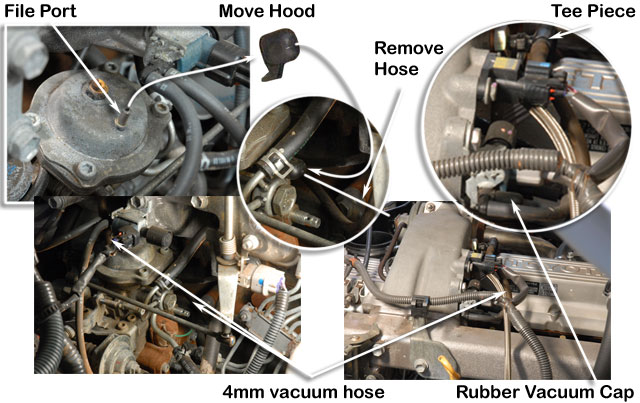
| With EGR: Remove the rubber hood from the top of the altitude compensator on the diesel injector pump.
File the top of the port until the central hole has enlarged to 2mm diameter. Remove the vacuum hose from the rear of the injector pump and the solenoid at other end. Install the rubber hood removed previously from the top of the pump to where the vacuum hose was originally fitted. Install the 4mm vacuum hose (Item 38) to the port on the top of the altitude compensator, route as shown and connect to the tee piece (Item 36).
|
 |
|||||||||||||||||||||||||||||||||||||||||||||||||||||||||||||||||||||||||||||||||||||||||||||||||||||||||||||||||||||||||||||||||||||||||||||||||||||||||||||||||||||||||||||||||||||||||||||||||||||||||||||||||||||||||||||||||||||||||||||||||||||||||||||||||||||||||||||||||||||||||||||||||||||||||||||||||||||||||||||||||||||||||||||
| 28 | Completion of Installation:
TUNING: See specifications below. Click here for tuning procedure.
|
|||||||||||||||||||||||||||||||||||||||||||||||||||||||||||||||||||||||||||||||||||||||||||||||||||||||||||||||||||||||||||||||||||||||||||||||||||||||||||||||||||||||||||||||||||||||||||||||||||||||||||||||||||||||||||||||||||||||||||||||||||||||||||||||||||||||||||||||||||||||||||||||||||||||||||||||||||||||||||||||||||||||||||||
| NOTES | ||||||||||||||||||||||||||||||||||||||||||||||||||||||||||||||||||||||||||||||||||||||||||||||||||||||||||||||||||||||||||||||||||||||||||||||||||||||||||||||||||||||||||||||||||||||||||||||||||||||||||||||||||||||||||||||||||||||||||||||||||||||||||||||||||||||||||||||||||||||||||||||||||||||||||||||||||||||||||||||||||||||||||||||
|
||||||||||||||||||||||||||||||||||||||||||||||||||||||||||||||||||||||||||||||||||||||||||||||||||||||||||||||||||||||||||||||||||||||||||||||||||||||||||||||||||||||||||||||||||||||||||||||||||||||||||||||||||||||||||||||||||||||||||||||||||||||||||||||||||||||||||||||||||||||||||||||||||||||||||||||||||||||||||||||||||||||||||||||