Safari Intercooler System SCHDJ80-24
| Parts List | |||||||||||||||||||||||||||||||||||||||||||||||||||||||||||||||||||||||||||||||||||||||||||||||||||||||||||||||||||||||||||||||||||||||||||||||||||||||||||||||||||||||||||||||||||||||||||||||||
|
|||||||||||||||||||||||||||||||||||||||||||||||||||||||||||||||||||||||||||||||||||||||||||||||||||||||||||||||||||||||||||||||||||||||||||||||||||||||||||||||||||||||||||||||||||||||||||||||||
| Installation Guide | |||||||||||||||||||||||||||||||||||||||||||||||||||||||||||||||||||||||||||||||||||||||||||||||||||||||||||||||||||||||||||||||||||||||||||||||||||||||||||||||||||||||||||||||||||||||||||||||||
| 1 | Remove the bumper bar (bull bar) from the front of the vehicle. Remove the grill, headlight surrounds and parking lights also. Unbolt the bonnet catch and remove the centre support brace which runs vertically from behind the bonnet catch, down to the lower radiator support panel. Likewise, remove the horns and horn mounting bracket. | ||||||||||||||||||||||||||||||||||||||||||||||||||||||||||||||||||||||||||||||||||||||||||||||||||||||||||||||||||||||||||||||||||||||||||||||||||||||||||||||||||||||||||||||||||||||||||||||||
| 2 | Remove the indicator light mounting panel from across the front of the vehicle. The centre mounting bracket will have to be removed from this panel, by carefully drilling out the spot welds or neatly cutting with tin snips. | ||||||||||||||||||||||||||||||||||||||||||||||||||||||||||||||||||||||||||||||||||||||||||||||||||||||||||||||||||||||||||||||||||||||||||||||||||||||||||||||||||||||||||||||||||||||||||||||||
| 3 | From inside the engine bay, remove the radiator overflow bottle and if fitted, the R.H.S. battery tray. The air cleaner lid and turbo air entry hose will have to be removed. The turbo compressor discharge duct and heater block assembly on the inlet manifold can be discarded, along with the accelerator cable bracket on the cylinder head. | ||||||||||||||||||||||||||||||||||||||||||||||||||||||||||||||||||||||||||||||||||||||||||||||||||||||||||||||||||||||||||||||||||||||||||||||||||||||||||||||||||||||||||||||||||||||||||||||||
| 4 | Loosen the power steering line at the steering box. Rotate the lines 30˚ anti-clockwise, (towards the engine) then re-tighten. | ||||||||||||||||||||||||||||||||||||||||||||||||||||||||||||||||||||||||||||||||||||||||||||||||||||||||||||||||||||||||||||||||||||||||||||||||||||||||||||||||||||||||||||||||||||||||||||||||
| 5 | Mark the centre of the duct hole in the radiator support panel, beneath the R.H.S. headlight. To mark the hole centre, measure up from the horizontal brace 80mm, measure outwards from the vertical brace 180mm. Where the two lines intersect is the centre point for the hole. (You may have to check your measurements 2 or 3 times to find the correct point). Once the centre point is found, cut the hole to 83mm diameter, using a holesaw. Deburr the hole and paint to prevent rust. Fit rubber edging around the hole (item 27). | ||||||||||||||||||||||||||||||||||||||||||||||||||||||||||||||||||||||||||||||||||||||||||||||||||||||||||||||||||||||||||||||||||||||||||||||||||||||||||||||||||||||||||||||||||||||||||||||||
| 6 | Remove the R.H.S. wheel and the rubber flap from the inner guard. Position the template (item 32) on the lower front corner of the inner guard. Mark around the edge of the template. Using an air hacksaw, cut and remove the marked section. Remove the two mounting bolts that hold the inner guard, to the bottom of the radiator support panel. Position the intercooler inlet duct mounting bracket (item 3) and secure using original bolts and spacer washers (item 39), if required. Hold the intercooler inlet casting (item 2) in position and check that the inner guard cut out has adequate clearance. If necessary, cut/file until the casting clears the bodywork. Remove the duct, de-burr the inner guard, then paint to prevent rust. | ||||||||||||||||||||||||||||||||||||||||||||||||||||||||||||||||||||||||||||||||||||||||||||||||||||||||||||||||||||||||||||||||||||||||||||||||||||||||||||||||||||||||||||||||||||||||||||||||
| 7 | Ensure that the radiator and air-conditioning condenser are clean and free of debris, before re-assembly commences. | ||||||||||||||||||||||||||||||||||||||||||||||||||||||||||||||||||||||||||||||||||||||||||||||||||||||||||||||||||||||||||||||||||||||||||||||||||||||||||||||||||||||||||||||||||||||||||||||||
| 8 |
Fit and secure the centre support bracket supplied by SAFARI (item 12). Refit the bonnet catch assembly. Ensure the bonnet opens and shuts correctly. |
||||||||||||||||||||||||||||||||||||||||||||||||||||||||||||||||||||||||||||||||||||||||||||||||||||||||||||||||||||||||||||||||||||||||||||||||||||||||||||||||||||||||||||||||||||||||||||||||
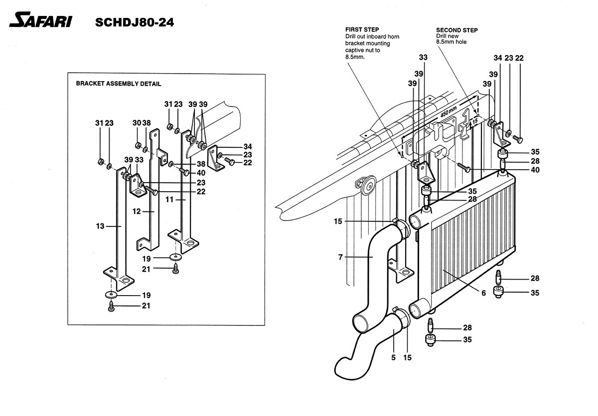
| 9 | Drill out the inboard horn mounting hole (the horn bracket hole closest to the bonnet catch) to 8.5mm. Measure from this hole across to the left side of the vehicle 450mm. Drill a new 8.5mm hole, 15mm up from the bottom edge of the panel. | ||||||||||||||||||||||||||||||||||||||||||||||||||||||||||||||||||||||||||||||||||||||||||||||||||||||||||||||||||||||||||||||||||||||||||||||||||||||||||||||||||||||||||||||||||||||||||||||||
| 10 | Loosely fit the mounting brackets (item 11, 13, 33, 34), using two spacer washers (item 39) between the outer brackets and the radiator support panel. Also, use two spacer washers (item 39) between bracket (item 11) and inside face of radiator support panel. Install the mounting pins (item 28) into position on the intercooler core assembly, using locktite (item 6).
Slide one rubber mounting bush (item 35) onto each pin. (The large side of the bush towards the intercooler core, the smaller side locates in the mounting bracket hole). Position the intercooler assembly on the vehicle and tighten the bracketry. Drill the lower holes for the mounting brackets, in the lower radiator support cross brace, to 4mm and secure the brackets using self tapping screws (item 19, 21). |
||||||||||||||||||||||||||||||||||||||||||||||||||||||||||||||||||||||||||||||||||||||||||||||||||||||||||||||||||||||||||||||||||||||||||||||||||||||||||||||||||||||||||||||||||||||||||||||||
| 11 | Remove the air conditioning line support bracket from the radiator support panel. Position the intercooler outlet casting (item 8) through the hole in the radiator support panel (long half inside the engine bay). Re-fit the air conditioning support bracket. | ||||||||||||||||||||||||||||||||||||||||||||||||||||||||||||||||||||||||||||||||||||||||||||||||||||||||||||||||||||||||||||||||||||||||||||||||||||||||||||||||||||||||||||||||||||||||||||||||
| 12 |
Fit the intercooler inlet duct (item 2) through the innerguard, bolting to the bracket (item 3) installed earlier using socket head bolt (item 24). Loosen the standard actuator from the standard actuator bracket. Install the spacer (item 41) between the actuator and the bracket. Re-fasten the actuator/bracket mounting bolts. |
||||||||||||||||||||||||||||||||||||||||||||||||||||||||||||||||||||||||||||||||||||||||||||||||||||||||||||||||||||||||||||||||||||||||||||||||||||||||||||||||||||||||||||||||||||||||||||||||
| 13 |
Position the silicone compressor discharge duct (item 1) on the compressor outlet and the top end of the intercooler inlet duct (item 2), together with clamp (item 14) at compressor end and clamp (item 15) at duct end. Bend the air conditioner line at the air conditioner compressor so the line will run along the outside of the silicone discharge hose (item 1). Ensure the power steering lines are clear of the discharge hose also. Adjust if necessary. |
||||||||||||||||||||||||||||||||||||||||||||||||||||||||||||||||||||||||||||||||||||||||||||||||||||||||||||||||||||||||||||||||||||||||||||||||||||||||||||||||||||||||||||||||||||||||||||||||
| 14 |
Install adaptor spacer (item 42) onto standard inlet manifold re-using standard gasket and hardware (items 43, 44). Fit the manifold inlet duct (item 10) using gasket (item 45) with the accelerator cable running underneath. Secure the duct using 8mm socket head bolts (items 24, 25, 26). Grind the top 3 ribs off the right hand side of the fan shroud. Fit the hose (item 9) from the manifold inlet duct (item 10) to the intercooler outlet duct (item 8), together with clamp (item 15) at manifold end and clamp (item 14) at lower end. Allow clearance between this hose and the fan shroud. Fit the mounting bracket (item 18) to the intercooler outlet duct (item 8). Drill a mounting hole in the radiator support panel to 7mm and secure using 6mm hardware (items 16, 17, 19, 30, 38, 40). |
||||||||||||||||||||||||||||||||||||||||||||||||||||||||||||||||||||||||||||||||||||||||||||||||||||||||||||||||||||||||||||||||||||||||||||||||||||||||||||||||||||||||||||||||||||||||||||||||
| 15 | Locate the 90˚ silicone air entry elbow (item 20) onto the turbo air entry. Use the top half of the standard rubber air entry duct and re-fit the air cleaner lid. Ensure all clamps are fastened. Fit the upper mounting bracket (item 4) on the intercooler inlet duct (item 2), using 6mm hardware (item 16, 17, 38). | ||||||||||||||||||||||||||||||||||||||||||||||||||||||||||||||||||||||||||||||||||||||||||||||||||||||||||||||||||||||||||||||||||||||||||||||||||||||||||||||||||||||||||||||||||||||||||||||||
| 16 | Connect the intercooler to the ducts using the rubber hoses (item 5, 7). The intercooler inlet (item 5) connects to the bottom of the intercooler, the intercooler outlet (item 7) to the top. Clamps (item 15) are used at the intercooler; clamps (item 14) are used at the duct ends. | ||||||||||||||||||||||||||||||||||||||||||||||||||||||||||||||||||||||||||||||||||||||||||||||||||||||||||||||||||||||||||||||||||||||||||||||||||||||||||||||||||||||||||||||||||||||||||||||||
| 17 | Ensure all hoses are positioned correctly, with no component under stress and appropriate clearances. Then tighten all eight ducting clamps (item 14, 15). | ||||||||||||||||||||||||||||||||||||||||||||||||||||||||||||||||||||||||||||||||||||||||||||||||||||||||||||||||||||||||||||||||||||||||||||||||||||||||||||||||||||||||||||||||||||||||||||||||
| 18 |
Remove the outer horn from the horn mounting bracket and bolt directly into position using the metal tag on the horn assembly. Re-connect to the wiring loom. Re-fit the radiator overflow bottle and R.H.S. battery tray if required. |
||||||||||||||||||||||||||||||||||||||||||||||||||||||||||||||||||||||||||||||||||||||||||||||||||||||||||||||||||||||||||||||||||||||||||||||||||||||||||||||||||||||||||||||||||||||||||||||||
| 19 | Re-assemble the front of the vehicle. Aftermarket bull bars may need to be modified to allow clearance for the intercooler connecting hose. | ||||||||||||||||||||||||||||||||||||||||||||||||||||||||||||||||||||||||||||||||||||||||||||||||||||||||||||||||||||||||||||||||||||||||||||||||||||||||||||||||||||||||||||||||||||||||||||||||
| 20 | Connect all test equipment (pyrometer, boost gauge, air/fuel ratio meter) and set up vehicle to specification. | ||||||||||||||||||||||||||||||||||||||||||||||||||||||||||||||||||||||||||||||||||||||||||||||||||||||||||||||||||||||||||||||||||||||||||||||||||||||||||||||||||||||||||||||||||||||||||||||||

